When most people think about access point performance, they think about chipset generations, radio count, or MCS rates. Sometimes even technical buyers are simply looking at the maximum throughput capabilities of an AP. But buried inside every AP, from the $30 device you find at Best Buy to a $2,000 enterprise powerhouse, is the component that actually matters as much as any other component, the antennas. Not all antennas are created equal. The antenna system is one of the most decisive separators between AP tiers, and understanding what's happening inside the fancy plastic enclosure can fundamentally change how you design, deploy, and troubleshoot wireless networks.
This article walks through the antenna continuum from the humble inverted-F etched on a budget AP's PCB all the way to RUCKUS's adaptive multi-element BeamFlex+ arrays. I'll explain why it matters for your deployments.
The Basics: What an AP Antenna Actually Does
Before diving into AP tiers, it helps to frame what we're asking an antenna to do. Every AP antenna provides three fundamental properties: gain, direction, and polarization. Gain indicates how much the antenna concentrates energy measured in dBi (decibels relative to an isotropic radiator, a theoretical antenna that radiates energy equally in all directions). Direction describes the shape of the radiation pattern. This describes whether the antenna blasts RF in all directions equally or focuses it in specific directions. Polarization defines the orientation of the electromagnetic field, which matters enormously for how well a client's antenna receives the signal (and how well the AP receives the response).
Understanding these three levers is key to comparing antenna designs. A gain of 2 dBi typically means a very flat, nearly omnidirectional pattern. An 8–9 dBi directional antenna concentrates energy in a narrow beam. What you gain in range and signal quality in one direction, you give up in coverage area elsewhere. Everything in AP antenna design is a tradeoff between these variables and, typically, the more you pay for an AP, the more sophisticated those tradeoffs become.
Tier 1: The Inverted-F and Its Cousins (Budget / Consumer APs)
At the bottom of the AP antenna ladder sits the Inverted-F Antenna (IFA) and its planar sibling, the Planar Inverted-F Antenna (PIFA). These are the workhorses of budget consumer and low-cost SMB access points. You'll find them as etched traces on a PCB, essentially a monopole antenna bent into an "F" shape and run parallel to a ground plane, shorted at one end and fed at an intermediate point.
The genius of the PIFA is its compactness. The design allows impedance matching to be controlled by the designer without external matching components, making it extremely cost-effective to produce at scale. A PIFA can be integrated directly into the AP's main circuit board: no external connectors, no cable runs, no mechanical parts. This is why practically every consumer Wi-Fi device (phones, laptops, cheap mesh nodes, and budget APs) uses some form of this antenna.
The tradeoffs are real, though. Inverted-F antennas have inherently narrow bandwidths, which becomes more problematic as Wi-Fi moves to wider channel widths (80, 160, and now 320 MHz in Wi-Fi 7). Gain is low. You will typically find these APs give only 2–3 dBi of gain. The radiation pattern, while usually omnidirectional, is often distorted by nearby PCB components, the ground plane, and even the plastic enclosure. For a device sitting on a shelf serving a small single-room apartment, this is sometimes acceptable. For a dense office, large venue, or client-dense MDU, it's a fundamental limitation.
Variants to know:
- IFA (Inverted-F Antenna): Classic single-wire bent element, common in legacy 2.4 GHz-only devices
- PIFA (Planar Inverted-F Antenna): Uses a flat top plate instead of a single wire, enabling multiband operation and slightly better bandwidth
- MIFA (Meandered IFA): Folds the radiating element to fit an even smaller PCB footprint
Tier 2: Dipole and Patch Antennas (Mid-Range SMB / Prosumer APs)
If we step up to the mid-market (Ubiquiti UniFi, TP-Link Omada, Aruba Instant On, and budget Cisco Meraki) you start seeing more deliberate antenna engineering. These APs typically move away from the IFA and toward dipole-based internal antennas or purpose-designed internal patch elements, often with dedicated antenna structures per band.
A dipole antenna offers an omnidirectional pattern in the azimuth plane (think of a donut shape around the vertical axis) and is typically a fit for ceiling-mounted APs that need to serve devices in all horizontal directions below. Internal dipoles in this tier are often designed as PCB traces or stamped metal elements, arranged in arrays to support MIMO spatial streams. A 4x4 MIMO AP at this tier will have at minimum eight antenna elements (two per spatial stream, typically arranged and tuned for cross-polarization diversity).
Patch antennas take a different approach: they concentrate energy forward and downward, sacrificing omnidirectionality for gain. A basic square patch antenna provides roughly 7–8 dBi of gain which is a measurable improvement over a PIFA's 2–3 dBi. Patch antennas are directional, making them suited for ceiling-mounted APs where most of the clients are in a cone in front of the antenna. Many mid-range APs designed for indoor enterprise use integrate patch-style elements internally, tuned for both 2.4 GHz and 5 GHz bands, and increasingly for 6 GHz in Wi-Fi 6E and Wi-Fi 7 products.
At this tier, you'll also encounter external antenna connectors on some models. Aruba's mid-range line and Cisco's Catalyst 91xx series both offer models with external connectors, allowing an operator to swap in directional or high-gain antennas for specific environments: a warehouse run with sector coverage or a large public venue (LPV) with overhead deployments, for example. For 6 GHz deployments, the FCC's AFC framework now permits standard power (SP) operation with directional external antennas, which has opened significant new design flexibility.
Key characteristics at this tier:
- Internal dipole arrays for MIMO, with dedicated elements per spatial stream
- Patch-style elements for ceiling-mount gain and downward focus
- Optional external RP-SMA connectors for antenna swapping
- Fixed radiation patterns with no dynamic adaptation
Tier 3: Fixed High-Performance Internal Arrays (Enterprise Mainstream)
Move into true enterprise territory and the antenna design complexity increases substantially. These APs field full internal MIMO antenna arrays designed from the ground up to support 4x4 or 8x8 spatial streams, tri-band operation (2.4, 5, and 6 GHz), and high channel utilization under dense client loads.
At this tier, every design decision matters. Antennas are cross-polarized (dual-polarization at ±45°) to improve diversity gain, reduce the impact of multipath fading, and better serve clients in varied orientations. The 5 GHz radio typically features a more directional downtilt pattern to reduce co-channel interference between APs on adjacent floors, while the 2.4 GHz radio maintains a broader pattern for legacy client compatibility. The 6 GHz elements are increasingly purpose-designed for that band's propagation characteristics: shorter wavelengths require physically smaller elements, but the cleaner spectrum pays dividends in efficiency.
Most enterprise APs at this tier also carry dedicated IoT radio hardware with its own antenna elements (typically BLE, with Zigbee or other 802.15.4 support on select models) enabling asset tracking, IoT device onboarding, and in some implementations, angle-of-arrival (AoA) location services. The practical implication for deployers is that the antenna count on an enterprise AP spec sheet is no longer just about Wi-Fi MIMO streams. A modern enterprise AP may carry 8 Wi-Fi antenna elements, dedicated BLE/IoT elements, and a separate scanning radio element, all in the same chassis.
What distinguishes this tier from Tier 2:
- Full 4x4 or 8x8 MU-MIMO antenna arrays per radio
- Cross-polarized dual-polarization elements for diversity
- Dedicated per-band antenna elements with optimized patterns for each frequency
- Dedicated spectrum scanning radio for interference classification and RRM
- BLE antenna arrays enabling location services and IoT onboarding
- RF management systems that leverage antenna receive-side data for system-wide optimization
Tier 4: Adaptive / Steerable Antenna Systems (Premium Enterprise)
Here is where antenna design stops being passive and starts being intelligent. The defining technology in this space is RUCKUS BeamFlex+, but it's worth understanding exactly what it does, and how it differs from software-based beamforming.
RUCKUS BeamFlex and BeamFlex+
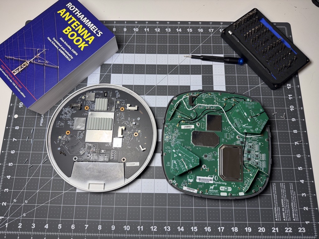
BeamFlex is a patented hardware antenna system consisting of up to 21 high-gain, directional antenna elements arranged in a compact internal array. On its own, a 21-element array can produce over 4,200 unique antenna patterns by activating different combinations of elements in real time. The AP's control software continuously evaluates each connected client and selects the antenna pattern combination that yields the highest data rate. Crucially, BeamFlex+ executes these pattern switches on a per-packet basis.
This is fundamentally different from 802.11 transmit beamforming (TxBF), which is a digital signal processing technique that adjusts phase and amplitude at the radio level to form a beam toward a specific client. TxBF is protocol-dependent and requires client support to be fully effective. BeamFlex/BeamFlex+, being a physical antenna switch, is completely standards-agnostic. It improves reception for every client regardless of whether that client supports beamforming. An 802.11n-only legacy device benefits just as much as a brand-new Wi-Fi 7 client.
BeamFlex also addresses one of the most overlooked problems in Wi-Fi: polarization mismatch. Because client devices (especially phones and laptops) change orientation constantly, a fixed-polarization AP may be transmitting in a polarization that the client's antenna can't receive well. BeamFlex activates elements in both horizontal and vertical polarizations simultaneously, ensuring the AP can always "hear" the client regardless of device orientation. The RUCKUS R770, its current flagship Wi-Fi 7 AP, combines BeamFlex+ with up to 4 spatial streams per radio across three concurrent bands. Many, in fact most, of RUCKUS's current AP lineup contain the BeamFlex+ technology, from wallplate to ceiling mount to outdoor APs.
Claimed benefits from RUCKUS on BeamFlex+ include up to 9 dBi of antenna gain from the adaptive array, up to 17 dB of interference rejection, and receive sensitivity down to -98 dBm (under optimal conditions). These figures far exceed what fixed internal arrays can achieve.
The Antenna Tier Comparison at a Glance
| Tier | Antenna Type | Typical Gain | Pattern | Adaptation | Example Products |
|---|---|---|---|---|---|
| Consumer/Budget | PIFA / IFA (PCB trace) | 2–3 dBi | Omnidirectional (fixed) | None | TP-Link home routers, cheap mesh nodes |
| SMB / Prosumer | Internal dipole arrays, patch elements | 3–6 dBi | Omni or directional (fixed) | None (optional ext. connectors) | Ubiquiti UniFi 6, Aruba Instant On AP22 |
| Enterprise Mainstream | High-performance MIMO arrays, cross-polarized | 4–6 dBi (internal) | Directional / downtilt (fixed) | Software RRM, dedicated scanning radio | Cisco Cat 9130, Aruba AP-635, Juniper AP43 |
| Premium Enterprise | Multi-element adaptive arrays | Up to 9 dBi (adaptive) | 4,200+ patterns (dynamic) | Per-client, per-packet switching | RUCKUS R, H, and T series APs |
Why This Matters for Your Deployments
The practical implications of antenna tier vary significantly by environment:
High-density environments (stadiums, auditoriums, convention centers, MDUs): Fixed omnidirectional antennas at this density are a nightmare: every AP is hearing its neighbors and clients are swimming in co-channel contention. This is exactly where BeamFlex-style adaptation or purpose-designed directional arrays shine. By focusing energy toward specific clients and away from co-channel neighbors, premium AP antennas dramatically reduce effective interference, allowing tighter AP spacing and higher client density.
Industrial and challenging RF environments (warehouses, manufacturing, hospitals): Metal shelving, forklifts, moving equipment, and RF-opaque materials wreak havoc on static antenna patterns. Adaptive systems that can continuously re-evaluate and select better paths around interference sources provide tangible, measurable benefits in these environments.
Standard office deployments: Honestly? A well-designed internal MIMO array at the enterprise mainstream tier is often sufficient. This is not to say that dynamic antenna arrays do not help, but the value proposition of premium antenna systems typically grows with density and RF complexity.
Outdoor / extended range deployments: Directional and sector antenna designs become critical outdoors, but mostly for long-range coverage. Often, outdoor APs are deployed simply for their resistance to the elements. For example, the coverage requirements in an MDU amenity space may be very similar to a high-density indoor deployment. In this use case, a dynamic antenna array could be more useful than a highly directional configuration.
Looking Ahead: Wi-Fi 7 and Antenna Evolution
Wi-Fi 7 (802.11be) introduces new antenna demands. Multi-Link Operation (MLO), the ability to transmit and receive simultaneously across multiple bands, requires that antenna arrays be simultaneously active across 2.4, 5, and 6 GHz, with careful isolation between elements to prevent self-interference. 320 MHz channel support in the 6 GHz band, while offering massive peak throughput, faces practical deployment challenges in enterprise environments due to the limited number of non-overlapping channels available, even in the wide-open 6 GHz spectrum.
The 6 GHz band itself presents a unique antenna design challenge: higher frequency means shorter wavelengths and smaller antenna elements, but also more challenging propagation through walls and obstacles. Designers are balancing element efficiency at 6 GHz against the need for the antenna to also serve 2.4 and 5 GHz clients on the same AP. Emerging compact multimode designs, like gap-coupled monopole antennas, are being published specifically to address this tri-band coverage challenge on a single, compact element.
Expect to see more software-switchable antenna configurations, more external 6 GHz antenna support, and continued investment in per-client adaptive antenna intelligence as the Wi-Fi 7 ecosystem matures.
Conclusion
AP antennas should not be an afterthought. They are the physical interface between your infrastructure and the air. The progression from a PCB-trace PIFA to a 21-element adaptive BeamFlex+ array represents an enormous gap in capability, and choosing the right tier for your environment is as important as choosing the right radio generation. Next time you're designing a deployment, don't just look at the hero throughput numbers. Look at the antenna count, the element type, whether there's any adaptation mechanism, and how the radiation pattern matches your physical space. That's where Wi-Fi lives or dies.
Tags: Wi-Fi, Enterprise Wireless, RF Design, RUCKUS BeamFlex, Antenna Theory, Wi-Fi 7, Dense Deployment, MDU, Large Public Venue, 802.11be, CWNE
Author: Alek Murray, CWNE #596